The welding neck flange bore (B) refers to the inside diameter of the flange that is designed to match the pipe’s outer diameter (OD). This precise alignment ensures a smooth, secure, and leak-proof connection. Welding neck flanges are widely used in high-pressure and high-temperature applications due to their ability to provide strong joints and excellent stress distribution.
Key Aspects of Welding Neck Flange Bores:
- Accuracy – The bore diameter must perfectly align with the pipe OD to prevent misalignment, ensure smooth fluid flow, and reduce turbulence.
- Standardisation – Manufactured in compliance with ANSI, ASME, and DIN standards, which define bore sizes for different flange classes and pipe schedules.
- Customisation – Special bore sizes can be manufactured to suit non-standard pipes or specific application requirements.
- Applications – Extensively used in industries where performance and reliability are critical, such as oil & gas, petrochemicals, and power generation.
- System Integrity – Selecting the correct bore size ensures long-term reliability, minimises stress on piping systems, and preserves overall system safety.
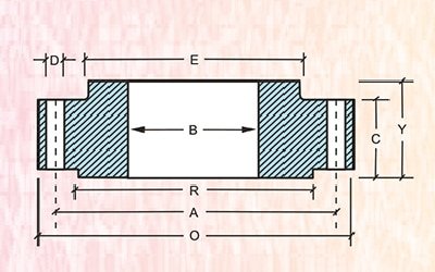
THREADED
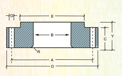
LAP JOINT
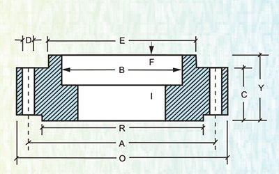
SOCKET WELD
| Welding Neck Flange Bores (B) | ||||||||||
| Nominal Pipe Size | Outside Diameter of Flange Hub | Sch 20 | Sch 30 | Std Wall | Sch 40 | Extra Strong | Sch 80 | Sch 120 | Sch 160 | Double Extra Strong |
| 15 | 21.33 | – | – | 15.7 | 15.7 | 13.8 | 13.8 | – | 11.7 | 6.4 |
| 20 | 26.67 | – | – | 20.8 | 20.8 | 18.8 | 18.8 | – | 15.5 | 11.0 |
| 25 | 33.40 | – | – | 26.6 | 25.4 | 24.3 | 24.3 | – | 20.7 | 15.2 |
| 32 | 42.16 | – | – | 35.0 | 35.0 | 32.4 | 32.4 | – | 29.4 | 22.7 |
| 40 | 48.26 | – | – | 40.8 | 40.8 | 38.1 | 38.1 | – | 33.7 | 27.9 |
| 50 | 60.31 | – | – | 52.3 | 52.3 | 49.2 | 49.2 | – | 42.8 | 38.1 |
| 65 | 73.02 | – | – | 62.4 | 62.4 | 59.0 | 59.0 | – | 53.9 | 44.9 |
| 80 | 88.90 | – | – | 77.9 | 77.9 | 73.6 | 73.6 | – | 66.6 | 58.4 |
| 100 | 114.30 | – | – | 102.2 | 102.2 | 97.1 | 97.1 | 92.0 | 87.3 | 80.0 |
| 125 | 141.30 | – | – | 128.1 | 128.1 | 122.2 | 122.2 | 115.9 | 109.5 | 103.2 |
| 150 | 168.27 | – | – | 154.0 | 154.0 | 146.3 | 146.3 | 139.7 | 131.7 | 124.3 |
| 200 | 219.07 | 206.2 | 204.9 | 202.7 | 202.7 | 193.6 | 193.6 | 182.5 | 173.0 | 174.6 |
| 250 | 273.05 | 260.3 | 257.4 | 254.5 | 254.5 | 247.6 | 242.8 | 230.1 | 215.9 | 222.2 |
| 300 | 323.85 | 311.1 | 307.0 | 304.8 | 303.2 | 298.4 | 288.8 | 273.0 | 257.2 | 273.0 |
| 350 | 355.60 | 337.8 | 336.5 | 336.5 | 333.3 | 330.2 | 317.5 | 300.0 | 284.1 | – |
| 400 | 406.40 | 390.3 | 387.3 | 387.3 | 381.0 | 381.0 | 363.5 | 344.5 | 325.4 | – |
| 450 | 457.20 | 441.1 | 434.9 | 438.1 | 428.6 | 431.8 | 409.5 | 387.3 | 366.7 | – |
| 500 | 508.00 | 488.9 | 482.6 | 488.9 | 477.8 | 482.6 | 455.6 | 431.8 | 407.9 | – |
| 600 | 609.60 | 590.5 | 581.0 | 590.5 | 574.6 | 584.2 | 547.6 | 517.5 | 490.5 | – |
Dimensional Tolerance
| Welding Neck | |||
| • Outside Diameter | O.D 600 or smaller | ±1.6 | |
| O.D. over 600 | ±3.1 | ||
| Inside Diameter (Bore) | 250 and smaller | ±0.7 | |
| 12 through 450 | ±1.6 | ||
| 500 of larger | +3.1 | -1.6 | |
| Diameter of Contact Face | 1.6 raised face | ±0.7 | |
| 6.3 raised face : tongue & | |||
| grooved male and female | ±0.4 | ||
| •Diameter of Hubat Base | When E is 600 or smaller | ±1.6 | |
| When E is over 600 | ±3.1 | ||
| Diameter of Hub at point | 125 and smaller | +0.7 | ±0.7 |
| of Welding | 150 and larger | +4.0 | ±0.0 |
| Thickness | 450 and smaller | +3.1 | 0.0 |
| 500 and larger | +4.7 | 0.0 | |
| Length through Hub | 250 and smaller | ±1.6 | |
| 300 and larger | ±3.1 | ||
| Bolt circle | ±1.6 | ||
| Drilling | Bolt hole spacing | ±0.7 | |
| Eccentricity with respect to bore | 0.7 max | ||
- All Dimensions are in Millimeters. Not Covered by ANSI-B 16.5
| Threaded, slip on, Lap joint socket welding, and Blind | |||
| • Outside Diameter | O.D. 50 or smaller | ±1.6 | |
| O.D. over 600 | ±3.1 | ||
| Inside Diameter (Bore) | Threaded : to standard gauge limits | ||
| Slip – on : lap jointso: cket – welding | |||
| 250 and smaller | +0.7 | 0.0 | |
| 300 and larger | +1.6 | 0.0 | |
| Threaded | |||
| Diameter of Counter Bore | 250 and smaller | +0.7 | 0.0 |
| 300 and larger | +1.6 | 0.0 | |
| • Outside Diameter of Hub | 300 and smaller | +2.3 | 1.6 |
| 350 and larger | ±3.1 | ||
| Diameter of Contact Face | 1.6 raised face | ||
| 6.3 raised face : tongue & | ±0.7 | ||
| grooved male and female | ±0.4 | ||
| Thickness | 450 and smaller | +3.1 | 0.0 |
| 500 and larger | +4.7 | 0.0 | |
| • Length through Hub | 250 and smaller | ±1.6 | |
| 300 and larger | ±3.1 | ||
| Bolt circle | ±1.6 | ||
| Drilling | Bolt hole spacing | ±0.7 | |
| Eccentricity with respect to bore | 0.7 max | ||


